Learning Overview
In this project, learners explore how technology can support better learning environments using Arduino and a sound sensor. They measure classroom noise levels and program alerts when sound becomes too high, helping everyone stay focused. We have included extra challenges that encourage learners to adjust sensitivity and alert styles, making learning fun and interactive. Through this hands-on experience, learners build data awareness, decision-making, and problem-solving skills while discovering how smart systems can promote respect, self-regulation, and positive shared learning spaces.
What You will Need
| Item | Purpose |
|---|---|
| Arduino Uno R4 WiFi | Controls the entire noise monitoring system |
| Breadboard | Allows easy connection of components |
| Sound Sensor Module | Detects noise levels |
| Red LED | Visual warning when noise is too loud |
| Buzzer (Active) | Sound alert for high noise |
| 220Ω Resistor | Protects the LED |
| Jumper Wires | Connect components together |
| USB Cable | Powers and programs the Arduino |
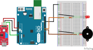
Understand the Circuit
Here is how each components connect:
Sound Sensor Module

VCC → connects to the 5V on the Arduino
GND → connects to the GND on the Arduino
OUT → connects to the Analog pin A0 on the Arduino.
This allows the Arduino to read sound levels as numeric values.
Red the LED
Noise Warning Light

Connect the long leg (positive/anode) of the LED to one end of the 220Ω resistor
Connect the other end of the resistor to digital pin 9 on the Arduino.
Connect the short leg (negative/cathode) of the LED to the GND on the Arduino.
The Buzzer
Sound the alarm when noise exceeds the safe level

Connect the positive (+) pin of the buzzer to digital pin 8 on the Arduino.
Connect the negative (–) pin of the buzzer to the GND rail.

The Project Code
Open the Arduino IDE on your computer and type this code:
int soundPin = A0;
int ledPin = 9;
int buzzerPin = 8;
int soundValue = 0;
int noiseThreshold = 600;
void setup() {
pinMode(ledPin, OUTPUT);
pinMode(buzzerPin, OUTPUT);
Serial.begin(9600);
}
void loop() {
soundValue = analogRead(soundPin);
Serial.println(soundValue);
if (soundValue > noiseThreshold) {
digitalWrite(ledPin, HIGH);
digitalWrite(buzzerPin, HIGH);
} else {
digitalWrite(ledPin, LOW);
digitalWrite(buzzerPin, LOW);
}
delay(300);
}
Uploading the Code
- Connect your Arduino Uno to your computer using the USB cable
- In the Arduino IDE, go to:
- Tools → Board → Arduino Uno
- Tools → Port → (Select your Arduino port)
- Click the Upload button (the right arrow icon).
- Watch your project come to life!
Understand the code
| Code | What It Does |
|---|---|
soundPin = A0 | Reads sound data from the microphone |
ledPin = 9 | Controls the warning LED |
buzzerPin = 8 | Controls the buzzer |
noiseThreshold | Sets the maximum allowed noise level |
analogRead() | Reads sound level as a number |
if (soundValue > threshold) | Checks if noise is too loud |
digitalWrite(HIGH) | Turns ON LED and buzzer |
digitalWrite(LOW) | Turns OFF alerts |
Troubleshooting the Code
LED or buzzer not working
Check pin numbers in the code
Ensure correct polarity of LED and buzzer
Alerts always ON
Increase the
noiseThresholdReduce microphone sensitivity
No Serial Monitor data
Set baud rate to 9600
Check A0 connection
What You Have Learned
How sound is measured using sensors
How Arduino converts sound into data
How to build alert systems using conditions
Why noise control matters in learning spaces
Basic electronics, coding, and teamwork skills
Extra Challenge
Add multiple LEDs (green, yellow, red) for noise levels
Display noise levels on an LCD screen
Add a reset button for teachers
Log noise data during the school day
Create classroom rules based on noise levels